
The ground connection evacuates fault currents to the ground to protect people and devices. Checking its proper functioning is a safety reflex, but not everyone has a multimeter at the bottom of a drawer. Several methods allow for a quick check of the presence and continuity of the ground in a home installation, without this measuring device.
Test Light and Voltage Tester: Two Substitute Tools to Check the Ground
The voltage tester screwdriver (neon screwdriver) is the most accessible tool. Its principle: a small neon lamp lights up when the tip touches a live conductor and the finger completes the circuit through the human body.
To test the ground, simply place the tip of the screwdriver on the ground pin of the wall socket. If the lamp lights up, a leakage current is flowing through this pin, indicating a problem (phase returned to ground, for example). If it stays off, the pin is not live, which is the expected behavior.
This test only confirms the absence of dangerous voltage on the pin. It says nothing about the actual continuity of the green/yellow wire to the ground rod.
To go further, a test light made of a filament bulb and two wires is helpful. Connect one wire to the phase (the right hole of the socket, looking at the pin on top) and the other wire to the ground pin. If the light turns on, the ground is properly connected and the circuit closes to the ground.
Several guides detail how to measure the ground connection without a multimeter by combining these two approaches for a more reliable diagnosis. The test light remains a binary indicator (on or off): it does not provide the ohm value of the ground resistance.
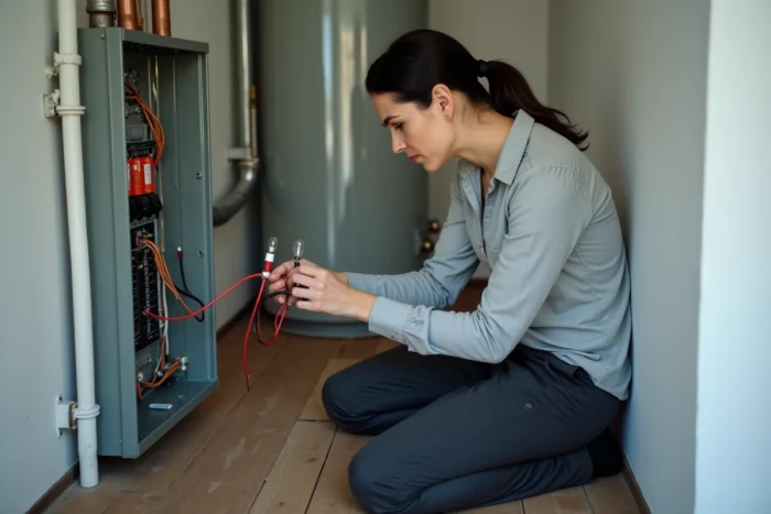
Wall Socket Tester: Quick Diagnosis Without Technical Knowledge
Plug-in socket testers, sold for a few euros in hardware stores, display a LED code that indicates the wiring status. Three indicators are enough to signal several common faults:
- Absence of ground (the corresponding LED stays off, meaning the green/yellow wire is not connected or is cut)
- Phase/neutral reversal (the combination of LEDs changes, revealing reversed wiring that does not necessarily trigger the residual current device)
- Correct wiring (the three LEDs light up according to the manufacturer’s code, confirming the presence of ground and the correct phase/neutral order)
This type of tester detects the presence of the ground wire, not its quality. A ground resistance that is too high will not be indicated by a simple plug-in tester. The fault current could take too long to trigger the residual current device, leaving a person exposed to electric shock for several hundred milliseconds.
Residual Current Device: An Indirect Test of Ground Continuity
The residual current device continuously monitors the difference between the current entering through the phase and the current exiting through the neutral. When a leakage flows to the ground, this difference exceeds the triggering threshold and the device cuts off the power.
A “Test” button is present on each residual current device in the electrical panel. This button simulates a calibrated leakage current. If the residual current device triggers when pressing it, the ground circuit is functioning at least partially. If nothing happens, two hypotheses: either the residual current device is faulty, or the ground is absent or cut.
Pressing this button once a month is a good habit. This action does not replace a resistance measurement, but it confirms that the protection chain (ground + residual current device) reacts correctly to a simulated leakage.
Limitations of the Test by the Residual Current Device Button
The “Test” button generates an internal leakage current within the device. It checks that the cutoff mechanism works, not that the ground rod has sufficient resistance. A residual current device can trigger correctly while the ground resistance is too high to ensure rapid protection in a real situation. Both checks are complementary.

Why These Methods Do Not Replace a Ground Resistance Measurement
All the techniques described here are tests of presence or continuity. They answer the question “Is the ground wire connected?” but not the question “Is the ground resistance low enough to protect the occupants?”.
The NF C 15-100 standard, updated in August 2024 with strengthened requirements for grounding, remains the reference for new installations and major renovations. Only a tellurimeter (or a equipped professional) can accurately measure the resistance in ohms and conclude on regulatory compliance.
For homes where the electrical installation is over fifteen years old, an electrical diagnosis is mandatory in case of sale, with a validity period of three years. This diagnosis includes checking the grounding by a certified professional, with appropriate instruments. A home test cannot replace this legal obligation.
- The test light and voltage tester check for the presence of voltage or the continuity of the ground circuit
- The plug-in socket tester detects the absence of ground and phase/neutral reversal
- The “Test” button on the residual current device confirms the functioning of the protection chain
- The tellurimeter, used by an electrician, is the only tool that measures ground resistance in ohms
A quick test with a light or socket tester remains useful for spotting a blatant fault, such as a disconnected ground wire after work. For any old installation or any doubt about the resistance value, calling an electrician with a tellurimeter is the only reliable approach.